AWS Certified Solutions Architect Associate SAA-C03
Tips: Create multiples AWS Account using 1 Email
0. Cloud, Networking and Technical Fundamental
OSI 7-Layer Networking Model
OSI Model
OSI 7-Layer Model
- Lower (Media) Layers: Physical, Data Link, Network – deal with how data physically moves between points (local or global).
- Upper (Host) Layers: Transport, Session, Presentation, Application – deal with how data is packaged, transmitted reliably, and interpreted by applications.
Data flows down the OSI stack on the sender’s side and up the stack on the receiver’s side. For example, a web browser on one end communicates with a web server on the other through these layers.
Diagram – OSI 7 Layers
- Host Layers (Top): Handle data formatting, reliability, and application logic.
- Media Layers (Bottom): Handle transmission and routing of data across networks.
Layer 1 - Physical
Layer 1 (Physical Layer) is the foundation of networking. It defines how raw bits (0s and 1s) are transmitted over a shared physical medium (copper, fiber optic, or wireless).
-
Key Concepts:
- Point-to-Point Links:
- Two devices (e.g., laptops) can communicate using a direct cable connection or by joining the same wireless network.
- Physical Mediums:
- Copper cable → electrical signals
- Fiber optic → light pulses
- Wireless (Wi-Fi) → radio frequencies
- Standards/Specifications:
- Define voltage levels, timings, data rates, distances, modulation methods, and connector types so that devices can interpret signals consistently.
- Point-to-Point Links:
-
How Communication Works
- Network Interface Cards (NICs) transmit bits as signals (e.g., 1 volt = binary 1, 0 volts = binary 0).
- Both devices must use the same physical standard to interpret signals correctly.
-
Expanding to Multiple Devices
- Hub (Layer 1 Device):
- A hub retransmits incoming signals to all other ports.
- Creates a shared medium for multiple devices.
- Forms one broadcast domain and one collision domain.
- Hub (Layer 1 Device):
-
Limitations of Layer 1
- No addressing: All transmissions are broadcast to everyone.
- Collisions: If two devices transmit at once, signals overlap and corrupt data.
- No Media Access Control (MAC): No rules to decide who transmits and when.
- No error detection or correction: Layer 1 cannot identify or recover from collisions.
- Poor scalability: More devices → higher chance of collisions.
-
Importance
- Layer 1 is fundamental: it enables the physical transmission of data.
- However, it lacks intelligence for reliable, directed communication.
- Layer 2 (Data Link Layer) builds on top of Layer 1 to provide addressing, access control, and error handling, making practical communication possible.
- Key Concept:
- Layer 1 defines the physical transmission environment for networking, but by itself only supports raw broadcasting without reliability or control.
- For effective networking, we need the intelligence of higher layers starting with Layer 2.
Layer 2 - DataLink
Role of Layer 2
- Sits above Layer 1 (Physical layer).
- Enables reliable device-to-device communication on the same network segment.
- Provides addressing, flow control, and error detection/correction.
Frames
-

-
Layer 2 introduces frames as the unit of communication.
-
Frame structure includes:
- Preamble & Start delimiter – identifies start of frame.
- Destination & Source MAC addresses – unique 48-bit hardware identifiers.
- EtherType field – indicates which Layer 3 protocol is encapsulated.
- Payload – actual data (often Layer 3 packets).
- Frame Check Sequence (FCS) – error detection via CRC.
-
Concept of encapsulation: higher-layer data is wrapped inside a frame.
Media Access Control
-
Solves the collision problem of Layer 1 shared mediums.
-
Uses CSMA/CD (Carrier Sense Multiple Access with Collision Detection):
- Check if medium is free before sending.
- Detect collisions, send jam signal, apply random backoff, retry.
-
Supports unicast (one-to-one) and broadcast (one-to-all).
Devices
-
Hubs (Layer 1): repeat signals blindly, cause collisions, all devices receive data.
-
Switches (Layer 2):
- Understand frames and maintain MAC address tables.
- Forward frames intelligently to the correct port.
- Each port is its own collision domain.
- Store-and-forward mechanism ensures only valid frames are delivered.
Benefits of Layer 2
- Provides unique device identification (MAC addresses).
- Enables controlled and reliable sharing of a medium.
- Reduces collisions and improves scalability (especially with switches).
- Forms the foundation for higher-layer protocols and the internet itself.
Layer 3 - Network
Purpose of Layer 3
- Enables communication across different Layer 2 networks (internetworking).
- Provides logical addressing, routing, and packet delivery between devices separated by multiple networks.
- Supports scalability beyond local LANs.
Packets and Encapsulation
- Layer 3 unit of data = Packet.
- Packets have source and destination IP addresses (can be global, unlike Layer 2).
- Encapsulation: IP packet is placed inside a Layer 2 frame for each hop.
- As packets move, frames change but the IP packet remains constant.
Key Fields in IP Packets
- Source IP & Destination IP – device identifiers.
- Protocol field – specifies Layer 4 protocol (e.g., TCP=6, UDP=17, ICMP=1).
- Time To Live (TTL) / Hop Limit – maximum hops before discard.
- Payload – data from Layer 4 protocols.
IPv4 vs IPv6
- IPv4: 32-bit addresses, dotted decimal (e.g., 133.33.3.7).
- IPv6: 128-bit addresses, larger space, similar structure but with Hop Limit.
- Both carry Layer 4 data inside.
IP Addressing & Subnetting
- IP address = Network part + Host part.
- Subnet mask (e.g., /16, 255.255.0.0) defines network vs host bits.
- Devices are local if network parts match; otherwise, communication goes through a router.
- Subnets allow calculation of network start and end addresses.
Routing and Route Tables
-
Routers forward packets between networks.
-
Each router has a routing table:
- Destination network (prefix).
- Next hop (where to send packet).
-
Default route (0.0.0.0/0) used if no specific match exists.
-
Routing can be static or dynamic (e.g., BGP).
Address Resolution Protocol (ARP)
- Translates IP addresses to MAC addresses for local delivery.
- Process: device broadcasts “Who has IP X?” → target replies with MAC address.
- Enables Layer 3 packets to be encapsulated in Layer 2 frames.
Example Scenarios
- Local communication: Devices use ARP to resolve MAC and send directly.
- Remote communication: Device sends packet to default gateway (router), which forwards it across multiple networks until destination is reached.
Limitations of Layer 3
- Provides only basic delivery (no sessions, no reliability).
- Packets can arrive out of order. No flow control, leading to possible congestion and packet drops.
- Cannot distinguish between multiple application streams on the same devices.
- These gaps are solved by Layer 4 protocols (TCP/UDP).
Layer 4 & 5
Layer 4 (Transport Layer) Functions
- Adds TCP (reliable, ordered, connection-oriented) and UDP (fast, connectionless, less reliable).
- Introduces segments, encapsulated in IP packets.
- Provides multiplexing via source/destination ports.
- Ensures ordering with sequence numbers and acknowledgements.
- Implements flow control using window size.
- Uses checksums for error detection.
- Can prioritize data with the urgent pointer.
TCP Architecture
- Client-server model with ephemeral ports (client) and well-known ports (server, e.g., 443).
- Bidirectional communication: each direction has its own source/destination port pair.
- Segments provide a reliable stream despite packet unreliability at Layer 3.
TCP Three-Way Handshake
- SYN: client sends initial sequence number.
- SYN-ACK: server responds with its own sequence number and acknowledges client’s.
- ACK: client acknowledges server’s sequence number.
- After this, both sides are synchronized and ready to exchange data reliably.
Sessions and State
- A session is the ongoing, stateful communication between client and server.
- Managed via TCP sequence numbers, acknowledgements, and connection state.
Stateless vs Stateful Firewalls
- Stateless (e.g., AWS NACLs): Require explicit rules for both directions (outbound and inbound).
- Stateful (e.g., AWS Security Groups): Track TCP connection state—allowing return traffic automatically once an initial connection is permitted.
Networking
Network Address Translation (NAT)
Purpose of NAT
- Solves the IPv4 address shortage by allowing multiple private devices to share fewer public IPs.
- Translates private IP addresses ↔ public IP addresses so private devices can access the internet.
- Provides basic security benefits by hiding internal private addresses.
- Not required in IPv6 (sufficient address space).
Types of NAT
1. Static NAT (One-to-One)
- Permanent mapping between a private IP and a specific public IP.
- Used when a device (e.g., server) must always be reachable on the same public IP.
- Example: AWS Internet Gateway.
2. Dynamic NAT (Many-to-Many, from a pool)
- Private IPs are temporarily mapped to available public IPs from a pool.
- Allocation happens only when needed.
- If the pool is exhausted, new connections fail.
- Suitable when public IPs are fewer than private devices, but not all need internet simultaneously.
3. Port Address Translation (PAT) / NAT Overload (Many-to-One)
-
Most common (e.g., home routers, AWS NAT Gateway).
-
Many private devices share one public IP.
-
Differentiates sessions using unique source ports.
-
Maintains a NAT translation table with mappings:
- (Private IP, Private Port) → (Public IP, Public Port).
-
Return traffic is correctly routed back using this table.
-
Limitation: inbound connections cannot be initiated directly to private devices (no entry in NAT table).
Key Points
- NAT operates only with IPv4 (IPv6 removes the need).
- Ensures private devices can access public services like Netflix or APIs.
- Static = fixed mapping, Dynamic = temporary pool mapping, PAT = many devices share one public IP via ports.
- Widely used in business networks, home routers, and cloud (AWS NAT Gateway/Instance).
IP Address Space & Subnetting
IPv4 Address Classes
-
Class A (0.0.0.0 – 127.255.255.255)
- 128 networks, each with ~16.7 million addresses.
- Historically allocated to large organizations (e.g., Apple, Ford, US Military).
-
Class B (128.0.0.0 – 191.255.255.255)
- 16,384 networks, each with ~65,536 addresses.
- Used by medium-to-large organizations.
-
Class C (192.0.0.0 – 223.255.255.255)
- Over 2 million networks, each with 256 addresses.
- Common for small businesses.
-
Class D (224.0.0.0 – 239.255.255.255)
- Reserved for multicast.
-
Class E (240.0.0.0 – 255.255.255.255)
- Experimental use.
Private IPv4 Address Ranges (RFC 1918)
-
10.0.0.0 – 10.255.255.255
- Single Class A block (~16.7 million addresses).
- Widely used in cloud platforms.
-
172.16.0.0 – 172.31.255.255
- Sixteen Class B networks (~65,536 addresses each).
- Default range for AWS VPCs.
-
192.168.0.0 – 192.168.255.255
- 256 Class C networks (256 addresses each).
- Common in home and small office networks.
Key Note: Private ranges cannot be routed on the internet and require Network Address Translation (NAT).
IPv6 Addressing
- Need for IPv6: IPv4 addresses are nearly exhausted due to rapid device growth and cloud services.
- Scale: IPv6 provides 340 undecillion addresses (3.4 × 10³⁸).
Subnetting Concepts
-
Definition: Subnetting divides a larger network into smaller networks, each with its own prefix length.
-
CIDR (Classless Inter-Domain Routing): Introduced prefixes (e.g.,
/16,/24) to describe subnet size. -
Principles:
- Larger prefix number = smaller subnet.
- Example:
10.0.0.0/16can be split into two/17networks, each covering half the range. - Repeated subdivision can produce multiple smaller subnets.
Distributed Denial of Service (DDOS) Attacks
Categories of DDoS Attacks
-
Application Layer Attacks (Layer 7)
- Examples: HTTP floods.
- Method: Attackers exploit computational imbalance—simple client requests trigger expensive server responses.
- Impact: Servers become overloaded, leading to performance degradation or failure.
-
Protocol-Based Attacks (Layer 3/4)
- Examples: SYN floods.
- Method: Exploit the TCP three-way handshake by sending spoofed SYN packets.
- Impact: Server holds connections in half-open state, consuming memory and network resources, preventing legitimate users from connecting.
-
Volumetric/Amplification Attacks
- Examples: DNS amplification.
- Method: Small requests (with spoofed victim IP) trigger disproportionately large responses from third-party servers to the victim.
- Impact: Saturates the victim’s network bandwidth, making services inaccessible even if servers remain operational.
VLANS, TRUNKS & Q-in-Q
What VLANs Solve
- A VLAN (Virtual Local Area Network) is a logical separation of devices on the same physical switch.
- Using VLANs, one switch can host multiple isolated networks.
- Each VLAN creates its own broadcast domain, so broadcasts don’t leak into other groups.
- Distinguish by VLAN ID (eg. Finance = VLAN 20, Game Testers = VLAN 10, Sales = VLAN 30)
802.1Q-Capable Switch (Managed Switch/VLAN Tagging)
-
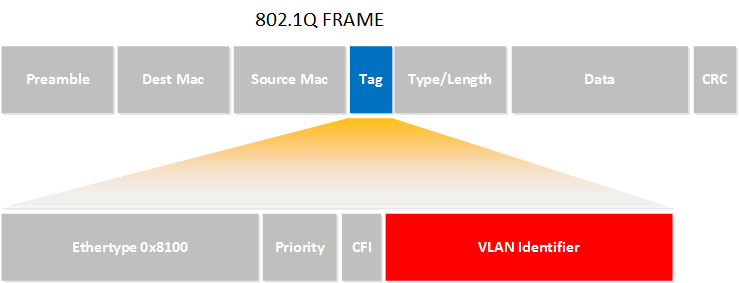
- Standard that makes VLANs work.
- It modifies the Ethernet frame to add a VLAN tag (12 bits) → supports up to 4096 VLANs.
- How it works:
- Devices connected to a switch don’t see VLAN tags.
- Switches add/remove tags internally to know which VLAN traffic belongs to.
- Access and Trunk ports apply when switch supports VLANs (via IEEE 802.1Q standard)
Access Ports vs Trunk Ports
-
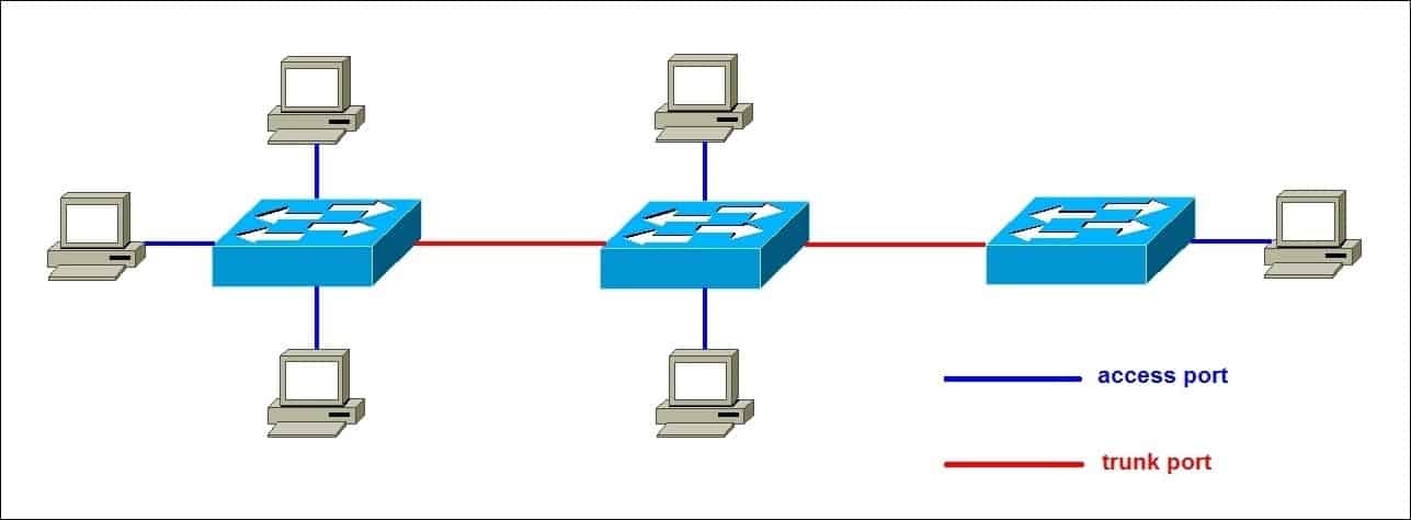
- Access Port
- Belongs to a single VLAN.
- Strips off the VLAN tag before sending frames to the end device.
- End devices (PCs, printers, phones) don’t need to understand VLAN tags.
- Trunk Port
- Carries multiple VLANs across a single link (usually switch-to-switch, or switch-to-router/firewall).
- Frames keep their 802.1Q VLAN tags while traveling over the trunk.
- The receiving device must also understand 802.1Q.
- Benefit: Access + Trunk ports allow VLANs to work across a network of switches instead of being stuck on just one switch.
Q-in-Q (802.1ad, VLAN Stacking)
-
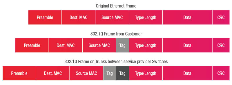
- Problem: What if you and your service provider both use VLANs? IDs might conflict (e.g., both use VLAN 1337).
- Solution: Q-in-Q = add a second VLAN tag
- VLAN in VLAN, Outer envelope = provider’s VLAN. Inner envelope = your VLAN.
Key
- 802.1Q define (VLANS)
- 802.1AD define (nested QinQ VLANS)
Decimal to Binary Conversion IPv4
Decimal to Binary Conversion (Complex Direction)
- Approach:
- Convert each octet (0–255) individually.
- Use a binary position value table: 128, 64, 32, 16, 8, 4, 2, 1.
- Rules:
- Rule 1: If the decimal value < binary position → write 0.
- Rule 2: If the decimal value ≥ binary position → write 1, subtract the binary position value from the decimal, and continue.
- Examples:
- 133 → 10000101.
- 33 → 00100001.
- Students practice converting 33 (third octet) and 7 (last octet).
- Final IP (133.33.33.7) in binary: 10000101.00100001.00100001.00000111.
Binary to Decimal Conversion (Easier Direction)
- Process:
- Break the 32-bit binary into four octets.
- For each octet, add the decimal values corresponding to binary 1 positions.
- Example:
- 10000101 → 128 + 4 + 1 = 133.
- 00100001 → 32 + 1 = 33.
- 00000111 → 4 + 2 + 1 = 7.
- Result:
- The binary IP converts back into the dotted decimal form.
SSL & TLS
Here’s a concise, topic-based summary of the video content you provided:
TLS/SSL Overview
- SSL vs TLS
- SSL = Secure Sockets Layer (older, less secure).
- TLS = Transport Layer Security (newer, secure replacement).
- Both provide privacy and integrity between client and server.
- Core Functions of TLS
- Encryption (Privacy): Protects communications so only client/server can read data.
- Authentication (Identity Verification): Ensures the server is the one it claims to be.
- Integrity: Detects and prevents alteration of data in transit.
TLS Handshake Process
- Cipher Suite Agreement
- Client sends Client Hello with supported cipher suites, TLS version, session ID.
- Server responds with Server Hello, selecting a cipher suite and sending its certificate (with public key).
- Authentication
- Server certificate is validated against trusted Certificate Authorities (CA).
- Checks include: CA signature, expiration, revocation status, and domain match.
- Client tests encryption using the server’s public key to ensure server holds the private key.
- Key Exchange
- Client generates a pre-master key, encrypts it with server’s public key, and sends it.
- Server decrypts using its private key.
- Both derive a master secret, used to create session keys.
- Session keys enable efficient symmetric encryption for ongoing communication.
Key Takeaways
- TLS uses asymmetric encryption initially, then switches to symmetric encryption for performance.
- Server identity is verified using CA-issued certificates.
- Final result: a secure, encrypted channel for client-server communication (e.g., HTTPS).
Border Gateway Protocol (BGP)
Purpose and Basics
- BGP: Routing protocol controlling data flow between networks.
- Used by AWS services such as Direct Connect and dynamic VPNs.
- Operates between Autonomous Systems (AS)—self-managed networks identified by AS Numbers (ASN).
- Runs over TCP port 179, providing reliability but requiring manual configuration of peering.
Autonomous Systems and ASNs
- ASNs: 16-bit numbers (0–65,535).
- Public: Allocated by IANA.
- Private: 64,512–65,534 (used in private peering).
- BGP views an AS as a black box—concerned only with routes in/out, not internal routing.
BGP Operation
- Path-vector protocol: Advertises only the best path (ASPATH) to destinations.
- iBGP: Routing inside an AS.
- eBGP: Routing between ASes (focus for AWS).
- Each AS shares routes with peers, building a distributed routing topology—this underpins the internet.
Example Topology (Brisbane, Adelaide, Alice Springs)
- Each site has its own ASN and IP range.
- Links:
- Brisbane ↔ Adelaide (1 Gb fiber).
- Adelaide ↔ Alice Springs (1 Gb fiber).
- Brisbane ↔ Alice Springs (5 Mb satellite).
- Routing tables: Initially list only local networks. After peering, each learns paths to others with ASPATH details.
- Multiple paths: BGP prefers the shortest path (fewest AS hops).
Path Control – ASPATH Pre-Pending
- BGP ignores link speed/latency, focusing only on path length.
- Example: Alice Springs can make its satellite link look worse by artificially adding extra ASNs (ASPATH pre-pending).
- This forces Brisbane to route traffic via Adelaide’s faster fiber link instead of the slower satellite.
Key Takeaways
- BGP builds a dynamic routing map of interconnected networks.
- Shortest path wins (based on AS hops, not performance).
- Supports high availability by automatically rerouting if a path fails.
- Core protocol behind the internet and hybrid networking solutions in AWS.
Stateful vs. stateless firewalls
TCP/IP Refresher
- TCP (Layer 4): Adds ports and error correction on top of IP.
- Connection structure:
- Request: Client → Server (ephemeral port → well-known port, e.g., 443).
- Response: Server → Client (well-known port → ephemeral port).
- Direction depends on perspective: same packet flow may be outbound for client, inbound for server.
Stateless Firewalls
- Treat request and response as separate flows.
- Require two rules for each connection: one for request, one for response.
- Responses use ephemeral ports, forcing wide port ranges to be opened.
- Higher admin overhead and greater security risk.
Stateful Firewalls
- Track the state of connections and link requests to responses automatically.
- Only the request rule needs to be defined; response is implicitly allowed.
- Do not require opening large ephemeral port ranges.
- Lower admin effort, fewer errors, more secure.
Key Takeaways
- Every TCP connection has two parts: request and response.
- Stateless firewalls: need explicit rules for both parts.
- Stateful firewalls: more intelligent, handle responses automatically, more secure and easier to manage.
Jumbo Frames
Consideration
- All devices in the path must support jumbo frames, otherwise fragmentation occurs.
- Not all AWS services/paths support jumbo frames.
Standard vs. Jumbo Frames
| Feature | Standard Frames | Jumbo Frames |
|---|---|---|
| Max Size | 1,500 bytes | ~9,000 bytes (AWS TGW: 8,500) |
| Efficiency | Higher overhead ratio | Lower overhead ratio |
| Frames Needed (same data) | More frames (less efficient) | Fewer frames (more efficient) |
| Use Case | General networking | High-performance, demanding apps |
AWS Jumbo Frame Support
| AWS Service / Path | Jumbo Frames Support |
|---|---|
| Within a single VPC | ✅ Supported (9,000 bytes) |
| Same-region VPC Peering | ✅ Supported |
| Inter-region VPC Peering | ❌ Not supported |
| VPN Connections | ❌ Not supported |
| Internet Gateway | ❌ Not supported |
| Direct Connect | ✅ Supported |
| Transit Gateway | ✅ Supported (up to 8,500 bytes) |
Application Layer Firewalls (Layer 7)
Background
- Layer 3 & 4 firewalls:
- See IPs, ports, flags, packets, and segments.
- Treat request/response as separate flows.
- Cannot inspect application data.
- Layer 5 firewalls:
- Add session awareness (link request and response together).
- Still no visibility into Layer 7 (application data opaque).
Layer 7 Firewall Capabilities
- Understands application protocols (e.g., HTTP, HTTPS, SMTP).
- Terminates encrypted connections (e.g., HTTPS → inspects HTTP in plaintext).
- Creates a new secure connection to the backend server (transparent to client/server).
- Can inspect, block, replace, or tag Layer 7 content.
Example Use Cases
- Filter/allow based on protocol elements: headers, DNS names, content type, connection rates.
- Protect against protocol-specific attacks or malformed traffic.
- Content control:
- Allow cat images, block malware/spam/adult content.
- Replace restricted content (e.g., adult images → kitten pictures).
- Application blocking (e.g., Facebook, Dropbox).
Key Points
- Retains all features of L3–L5 firewalls.
- Adds granular, content-aware security at the application layer.
- Effectiveness depends on which protocols the firewall supports.
IPsec VPN
IPsec

- Purpose: Secure tunnels over the internet → authentication, encryption, integrity.
- Use Cases: Site-to-site, AWS VPN, hybrid networks.
- Trigger: “Interesting traffic” starts a tunnel.
Phases
-
IKE Phase 1
- Purpose: Authenticate peers and establish secure channel.
- Methods: Pre-shared keys or certificates.
- Uses Diffie-Hellman exchange to derive a shared symmetric key.
- Result: Phase 1 tunnel / Security Association (SA).
-
IKE Phase 2
- Purpose: Negotiate encryption methods and set up tunnel for data transfer.
- Builds on Phase 1 tunnel.
- Creates IPsec keys for bulk encryption.
- Result: Phase 2 tunnel / IPsec SA pair (one for each direction).
VPN Types
-
Route-based:
- Matches traffic by prefix (e.g., 192.168.0.0/24).
- One SA pair (phase 2 tunnel) for all traffic between sites.
- Simpler setup, less flexible.
-
Policy-based:
- Matches traffic by rules/policies.
- Different SAs per traffic type (e.g., infra, CCTV, finance).
- More complex, more flexible security.
Key Point: Phase 1 = identity + key exchange, Phase 2 = data encryption. Route-based = simple; Policy-based = granular.
Fiber Optic Cables
Basics
- Fiber vs Copper:
- Copper → electrical signals.
- Fiber → light through glass/plastic core.
- Advantages: higher speeds, longer distances, EMI resistant, consistent performance.
- Widely used in LAN, metro, and global networks; adoption increasing.
Structure
- Core: Tiny glass/plastic strand (carries light).
- Cladding: Surrounds core; lower refractive index → keeps light inside by reflection.
- Buffer: Coating/strength material for protection.
- Jacket: Outer visible layer, color-coded (indicates cable type).
Fiber Types
-
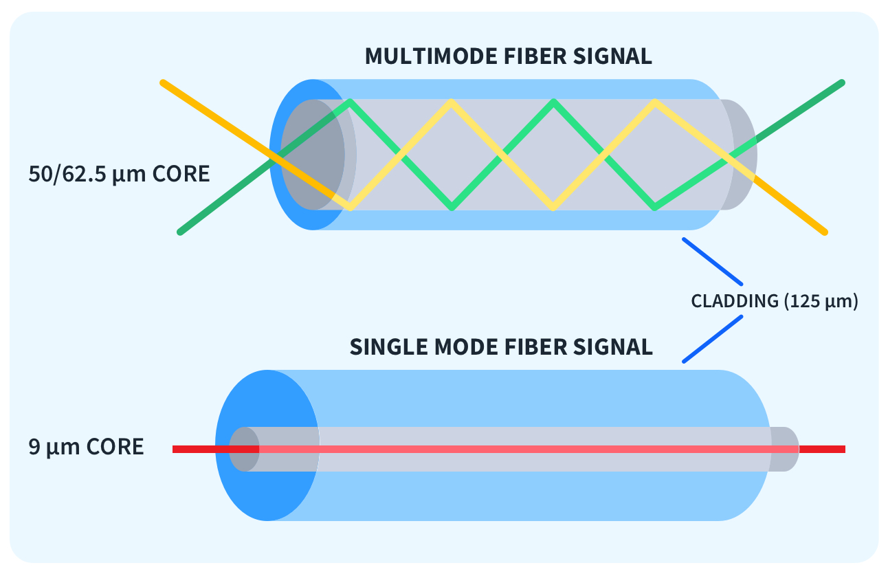
- Single-Mode (SMF)
- Core: ~8–9 microns, usually yellow jacket.
- Light path nearly straight → minimal distortion.
- Uses lasers, longer distances, high speeds (10 Gbps+ over km).
- Cable cheap, optics expensive (but prices falling).
- Multi-Mode (MMF)
- Core: larger (e.g., 50–62.5 microns), orange/aqua jacket.
- Multiple light paths → faster over short distances but more distortion at long distances.
- Uses LED optics, cheaper, shorter runs.
- Standards: OM2, OM3, OM4, etc.
Transceivers (SFP / Mini-GBIC)
- Plug into networking equipment to convert light ↔ data.
- Must match fiber type (SMF or MMF) on both ends.
- Common standards: 1000BASE-LX, 10GBASE-LR, 100GBASE-LR4 (used in AWS Direct Connect).
Key Point:
- Single-mode = long distance, high speed, higher optic cost.
- Multi-mode = short distance, cost-effective, simpler.
- Both rely on transceivers matched to cable type and connector.